Skip to content
Faulhorn Engineering Works
  • Projects
  • About
quarinjection

Quarinjection Ignition

  • May 30, 2020July 1, 2020
  • by Christian Stanton

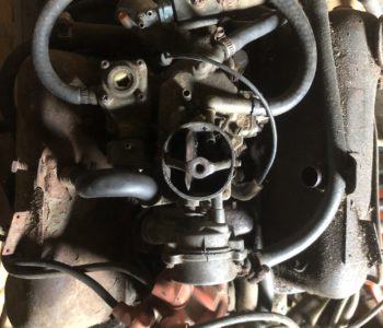
The ignition coil generates spark and the distributor distributes it to each spark plug. The distributor also varies the timing of the spark based on the speed of the engine (via a set of centrifugal weights) and the load / requested speed of the engine (via the vacuum advance).

The ECU will now control the timing of the ignition, so I only need to generate a spark and get it to the right spark plug. Modern EFI no longer uses the mechanical distributor but individual coils to deliver spark. You can use one coil for each plug or one coil for two plugs (wasted spark).

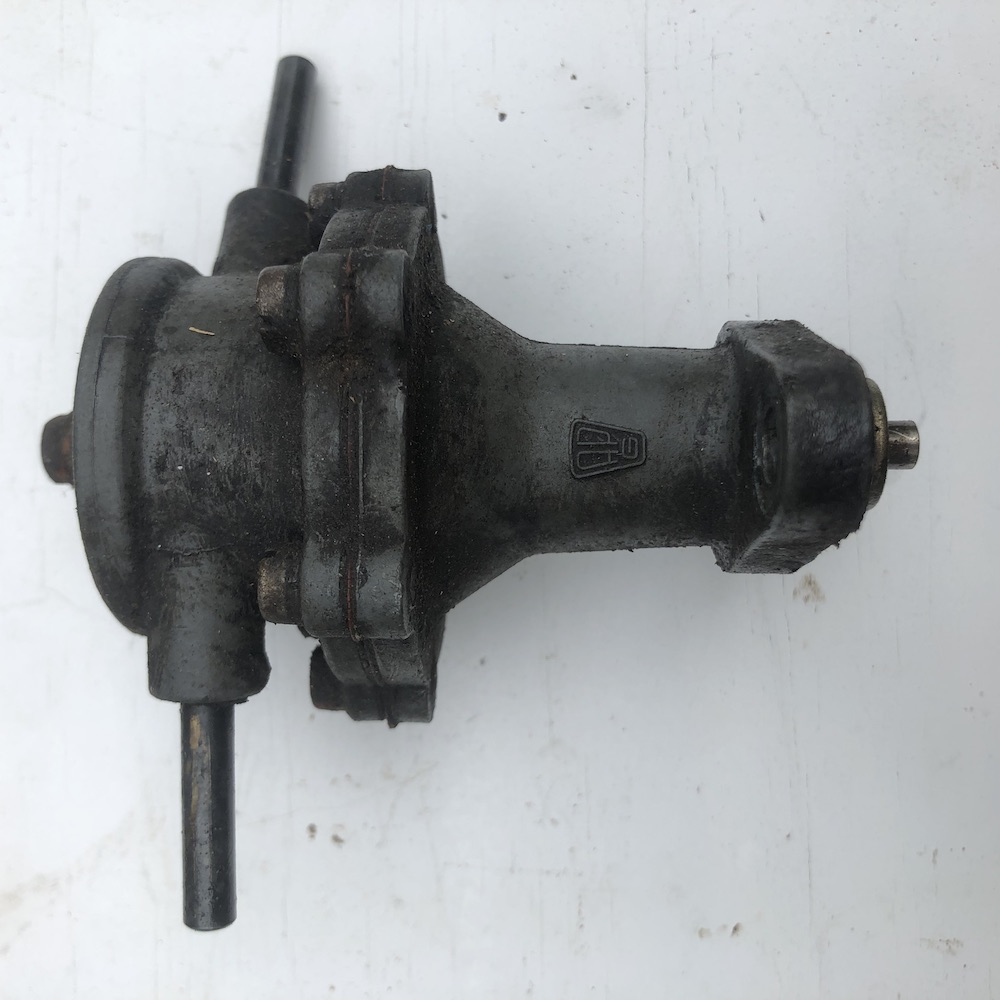
Neutering the distributor: It made sense to put the coil pack in the same place that the old distributor was located but first I had to eliminate the distributor. It can’t just be removed as the shaft also drives the oil pump.

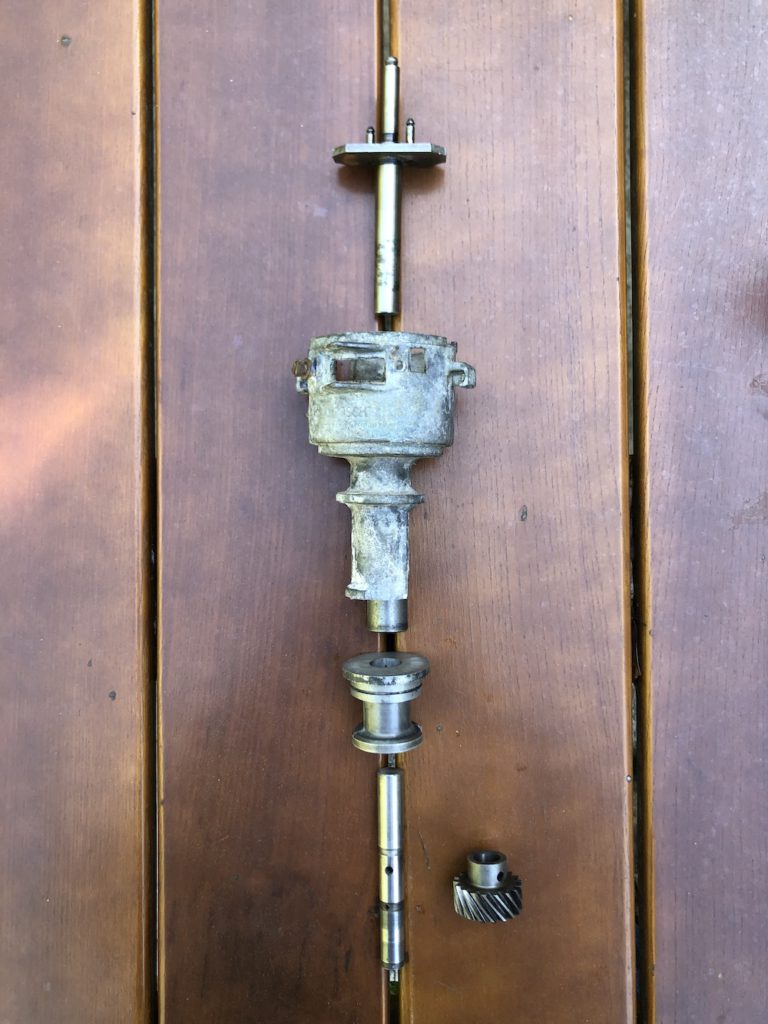
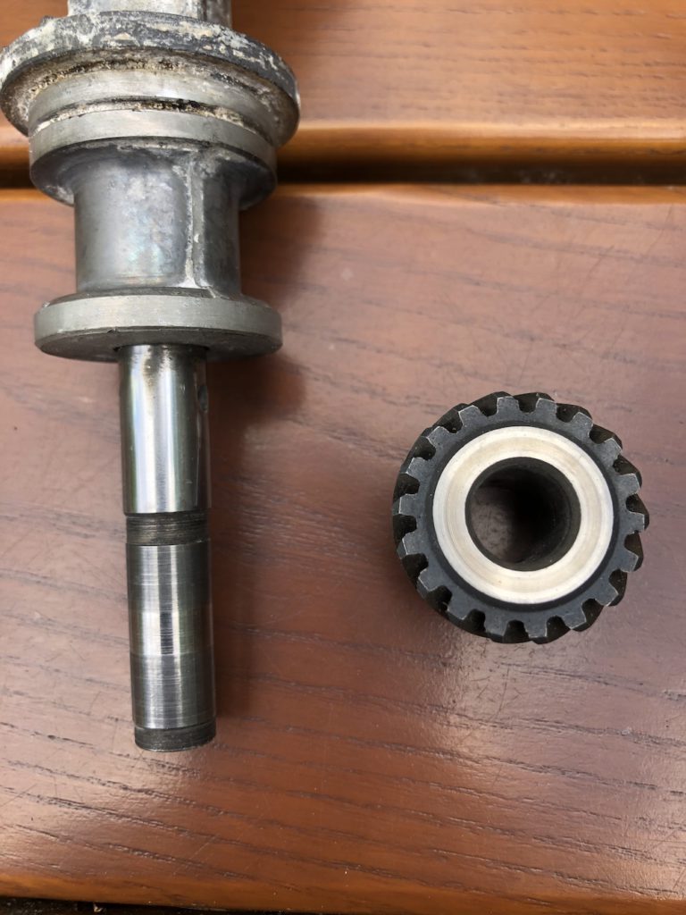
I cut the distributor housing at the flange and shortened the shaft to sit slightly below the surface of the housing. The lower shaft is supported by an oil pressure bearing. The shaft is thrust downward by the gear geometry and there is an axial bearing surface on the gear. There is a bushing in the top of the distributor housing which I felt was unnecessary now that there is little stress on the shortened shaft.

I’ll fabricate a cover and gasket for flange.

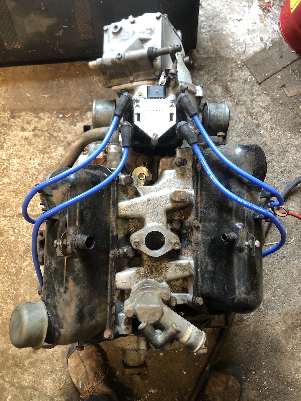
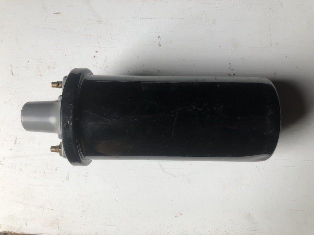
Spark source: I needed a coil that supported 4 cylinders and had a built in igniter. The igniter isolates the high voltage circuit and provides a low voltage interface to the ECU. I chose an ignition pack from 1998-2001 Volkswagen Golf for $15.

I fabricated a mount from sheet steel to locate it near the old distributor location.

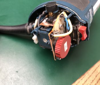
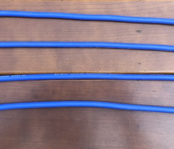
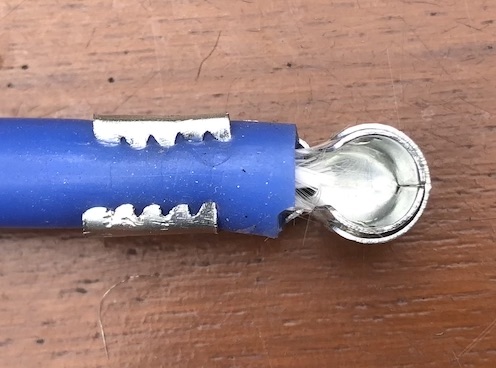
Spark delivery: I thought I was going to be able to reuse the ignition wires, but the plugs on the coil are different. The most cost efficient way to replace them was to buy a set of VW/Audi wires ($18) that were compatible with the coil pack and replace the spark plug ends with the correct plug socket ($7). Although there are specialized crimpers, you can get away with some artful work with needle nose pliers. The core is just folded back over the wire.

Ready to be hooked to the ECU!

You can see the top of the distributor flange and shaft just below the coilpack.

quarinjection

Quarinjection Fuel Pump

  • May 29, 2020July 1, 2020
  • by Christian Stanton

Modern fuel injection systems run at ~45PSI, much higher than the ~4PSI supplied by the existing mechanical pump. The easiest solution would have been an external pump hooked to the existing fuel line but this wound up more expensive than using a common submerged in-tank pump.

The existing Sonett fuel tank sits directly behind the driver and is an unusual shape for a tank. It is tall and narrow rather than flat.

The tank is ~14″ deep. After a lot of research and cost optimization later… a Chevy 1500/2500/3500 fuel pump from 1997-2000 has the correct size and fuel layout. It is an unregulated pump with a return and vent line with a roll-over valve and correct depth. The supply volume and pressure will work for the regulator and injectors I’m using. As a bonus it includes a fuel level sensor. All for $28! (see below)

The shape of the top of the tank is too narrow to fit the mounting hole for the pump and there is very limited clearance on top of the tank, so I had to recess a flange into the tank.

DO NOT WELD FUEL TANKS! (without knowing exactly what you are doing!). This tank was dry for 15 years and washed out with water based degreaser. If I had any doubt I would have filled the tank with water up to the part I was welding.

Lesson learned: After a bit of ugly MIG welding (and I ground the welds which was a mistake and then re-welded them which was another mistake), The welds were porous and would not seal up. I resorted to a coating POR-15 fuel tank sealer inside and out to seam seal the welds.

Designing the mount: Normally these pumps have a formed flange and a twist lock retaining ring. This is not something that is easily sourced without buying an entire fuel tank. (although I found something close here) I used a design used for other flange mounts with a split internal ring with captured nuts and an external ring to retain the pump. A flat flange seal (below in white) seals the pump to the tank.

Design for Fuel Pump Mount

Fail/Revise/Repeat: I built a split “C” ring of sheet steel and welded M5 captured nuts to it. The gauge on the steel was too light and the M5 about as small as I could weld with MIG. After installation, I realized that the large flat flange seal would not seal up with the amount of pressure that I could torque the screws to and the gap in the “C” ring left part of the flange unsupported. Lesson learned: A small footprint seal (like an o-ring) works better with low pressure flanges and non-machined surfaces.

I looked at how the original seal worked. It is a sleeve that fits the diameter of the pump with a compressible o-ring-like seal at the top. The pump hat has a second step that provides a small edge for a sealing surface. The seal did not come with the pump, so I had to source one (OEM was cheapest…$13).

OEM Fuel Pump Seal

I redesigned the inner ring in aluminum and used rivet nuts to provide the threads for the retaining bolts. The inner radius of the ring had to function as the outer sealing surface, so I split the thickness around two of the rivet nuts to provide half rings I could assemble inside the tank. Lesson learned: rivet nuts will distort aluminum! …I had to tediously bend the ring back to round.

New inner mounting ring with split, before rivet nuts

Final Assembly/Retrospect: During the final assembly, I used Permatex Motoseal to seal the inner ring to the tank and the threads (do not use RTV where permanently exposed to fuel!). The existing fuel level float was removed (it was broken anyway) and the one on the new pump altered to reverse the float to clear the inside of the tank. The range for fuel sensor will be reversed but I don’t plan on driving the fuel gauge directly. The original fuel feed at the bottom of the tank was soldered shut.

There was way too much fettling with this assembly! I had to manually correct for sloppy work (or sloppy corrections to good work). The inexpensive pump wound up being more expensive than buying one which included the seal and electrical plug. Ultimately, the design got there and it will work.

Final Pump Mount (Sealed!)
Top electrical connections are left:fuel pump and fuel level (combined) and right: tank pressure (for emissions, unused in this application).
Bottom connectors are left: fuel feed, center: vent and right: fuel return.

quarinjection

Quarinjection Basic Requirements

  • May 28, 2020July 1, 2020
  • by Christian Stanton

It would be easier to build out the Quarinjection project if I just sourced a bunch of parts designed for the DIY-EFI/Hotrod market. However, one of the challenges of this project was to design robustly on as thin a budget as possible. I sourced off the shelf items designed for high volume production cars which will make the engineering/integration more challenging, but lower the overall cost by allowing me to source from any suitable vehicle and aftermarket manufacturers.


What is needed to run an engine with Electronic Fuel Injection? It’s no different than the 60’s technology that the engine runs on now. You need the proper ratio of fuel and air and a well timed spark.

Existing Engine

Fuel Delivery – Pump: The little V4 has a physical diaphragm fuel pump driven by an eccentric lobe on the camshaft. This sucks gas from from the fuel tank and delivers a few PSI of pressurized fuel to the carburetor.

Fuel Delivery – Carburetor: The V4 has a Solex 28/32 PDSIT-4 carburetor. This regulates the amount of fuel by taking into account the temperature and load on the engine as well as the movement of the accelerator pedal. The carb functions as both ‘sensors’ and the ‘control mechanism’. It is an analog calculator.

Spark Delivery – Generation: The spark is supplied by the ignition coil. It’s similar to transformer (with a trick) to go from 12 volts to 40,000-50,000 volts. The trick is that when you remove the supply voltage from the coil, the magnetic field collapses and generates the high voltage spark.

Spark Delivery – Timing: The V4 has a Bosch distributor which regulates timing of spark based on engine RPM and engine load. It is another analog calculator.

Electronic Fuel Injection

To replace the functions of the existing engine with modern EFI, these are the elements needed:

  • Fuel Delivery
    • Fuel Pump
    • Fuel Lines
    • Injectors
  • Spark Delivery
    • Ignition
  • Sensors for engine load, timing and temperature
    • Throttle Position Sensor (TPS)
    • Manifold Pressure (MAP)
    • Crankshaft Position Sensor
    • Camshaft Position Sensor
    • Inlet Air Temperature (IAT)
    • Coolant Temperature (CLT)
  • An ECU computer to coordinate the sensors and delivery
    • Computer Selection

CNC

Router Hacking

  • May 27, 2020November 2, 2020
  • by Christian Stanton

In starting the Quarinjection project, I knew that it involved some custom fabrication of brackets, covers, etc. One of my existing skills and resources was a small CNC router that I built a few years ago from an Openbuilds OX design. Ideally I could CNC some aluminum parts. It’s perfectly capable of cutting aluminum, it’s just a trickier material than wood.

The problem: The spindle I have is a 1hp Bosch Colt PR20EVS router. The Colt works well for routing wood but aluminum requires a much lower spindle speeds. The stock Colt router runs 16K-35K RPM. Too high a surface speed (speed of the flute through the material) to cut chips and not just stir weld the aluminum (which I did a lot of trying to get this to work). I needed a maximum minimum(?) speed of around 10K RPM to achieve a surface speed of ~350ft/min with an 1/8″ bit. (The ideal speed for 6061 Aluminum is about 280SFM)

The Colt has a built in speed controller (via a thumb dial at the top) which I figured I could modify to lower the minimum speed without making it unusable. The motor is a 110v AC brushed which have limited torque ranges, so I’d be sacrificing a bit of torque at lower speed.

I measured the speed before taking it apart. (I’m measuring off of the collet nut, but one flat is painted white).

Stock minimum speed was 13K, lower than the spec 16K.
Maximum was also lower than the spec at ~30K.

Surgery!

Hard to see, but the chip on the left is an Atmel U2008B – Low cost AC Phase Controller.
I was never able to identify the other chip, but my guess is some sort of opamp.

Time for a bit of reverse engineering… luckily a simple single sided board which was not buried in potting compound. The core of the speed control is an Atmel U2008B – Low Cost AC Phase Controller. The chip is the one on the left in the picture above. This manages speed via phase shift and provides soft start and some load correction (so as the router gets loaded the RPM stays the same). The large Triac on the heat sink at the top of the board does the load switching.

The Red thumb wheel, a 2.5Kohm rheostat, is in series with a base resistor R7, which measures 2.5Kohm. Setting 1 is 5K=13000RPM, and setting 6 is 2.5K=30000RPM.

The marking on the SMD resistor of 398 threw me for a while (3900MOhm?), but this is a EIA-96 coded resistor sloppily marked 39D=2.49K. These resistors are 0603 sized (6mm x 3mm) which is hard to show just how tiny this is (think grain of pepper sized). Resistor assortments are available and inexpensive ($0.01/ea)

Minimum speed was at 5K total resistance, maximum at 2.5K so an increase in resistance would reduce the overall speed. Replacing R7 with the next stock value of 3.3K (EIA-96 51D) for a total resistance of 6.3K. This should give me a 25% (6.3K/5K) reduction in speed overall or 10,400K RPM minimum (assuming it’s roughly linear). To jump to the next value (5.1K) that I had on hand meant the adjustable range would get too low.

A bit of finicky soldering later…

Speed reduced to 10,300RPM minimum. Maximum is now about 21K RPM.

Success! The router doesn’t seem to be bothered by the change and runs normally at the lower speed. Off to cut aluminum!

Afterthought: I will eventually buy a true CNC spindle for this rather than mucking around with modifying a router, but for $8 I was able to get this to work.

Recent Posts

  • Realistic STA-2100D Restore
  • GRBL32, STM32 and other frustrations
  • CNC gets Smart(er) Servos… not
  • Quarinjection Selecting an ECU
  • Quarinjection Throttle Position Sensor

Recent Comments

    Archives

    • April 2022
    • November 2020
    • October 2020
    • July 2020
    • June 2020
    • May 2020
    • March 2020

    Categories

    • CNC
    • projects
    • quarinjection
    • stereo recap
    Theme by Colorlib Powered by WordPress