 quarinjection
Quarinjection Fuel Pump
Modern fuel injection systems run at ~45PSI, much higher than the ~4PSI supplied by the existing mechanical pump. The easiest solution would have been an external pump hooked to the existing fuel line but this wound up more expensive than using a common submerged in-tank pump.
The existing Sonett fuel tank sits directly behind the driver and is an unusual shape for a tank. It is tall and narrow rather than flat.
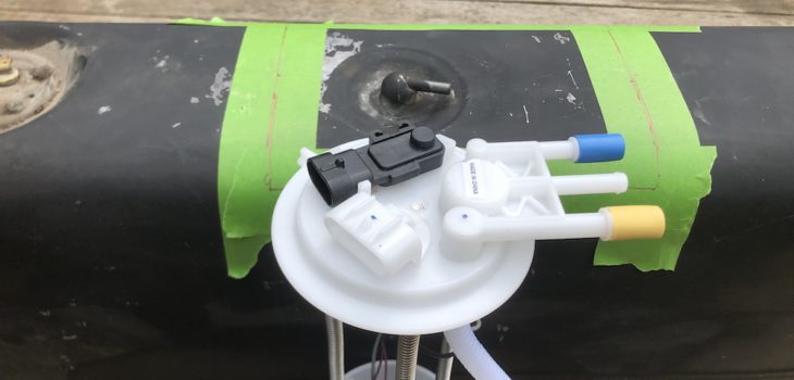
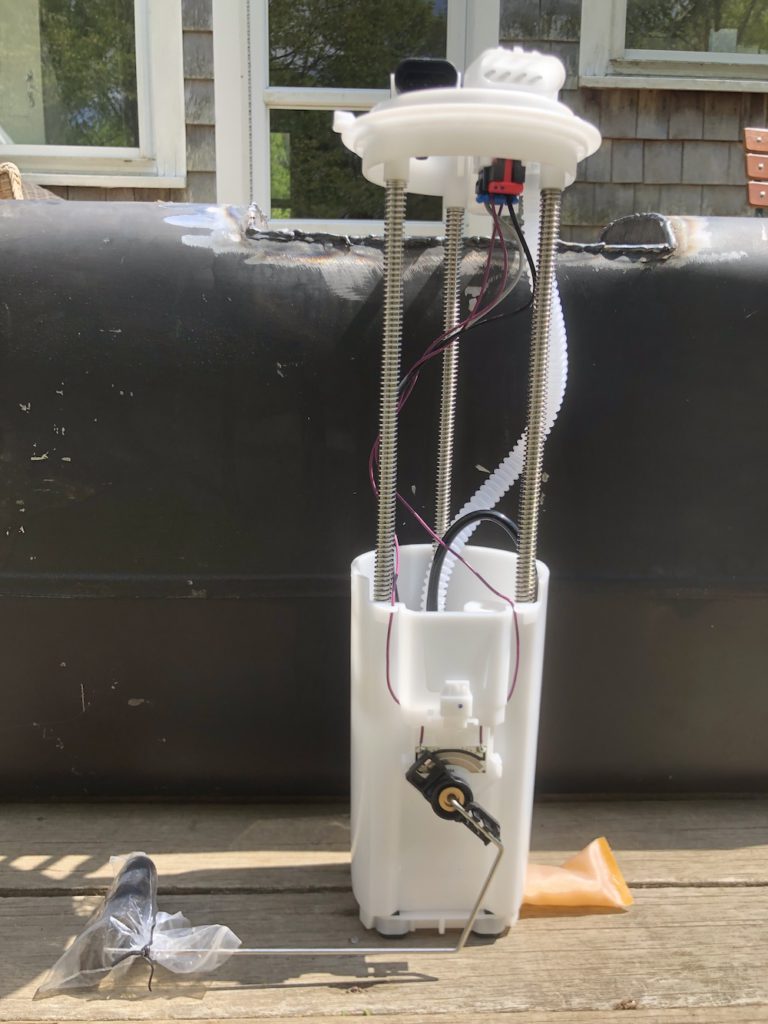
The tank is ~14″ deep. After a lot of research and cost optimization later… a Chevy 1500/2500/3500 fuel pump from 1997-2000 has the correct size and fuel layout. It is an unregulated pump with a return and vent line with a roll-over valve and correct depth. The supply volume and pressure will work for the regulator and injectors I’m using. As a bonus it includes a fuel level sensor. All for $28! (see below)
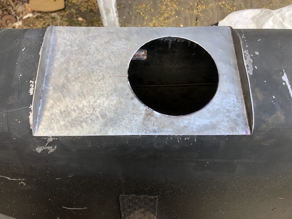
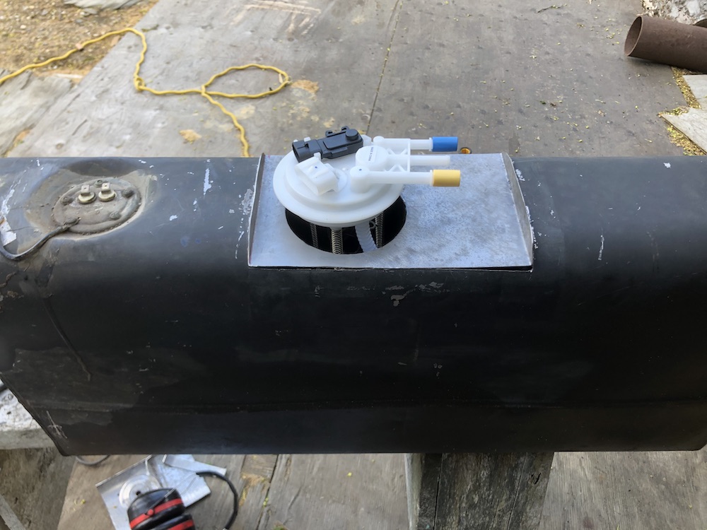
The shape of the top of the tank is too narrow to fit the mounting hole for the pump and there is very limited clearance on top of the tank, so I had to recess a flange into the tank.
DO NOT WELD FUEL TANKS! (without knowing exactly what you are doing!). This tank was dry for 15 years and washed out with water based degreaser. If I had any doubt I would have filled the tank with water up to the part I was welding.
Lesson learned: After a bit of ugly MIG welding (and I ground the welds which was a mistake and then re-welded them which was another mistake), The welds were porous and would not seal up. I resorted to a coating POR-15 fuel tank sealer inside and out to seam seal the welds.
Designing the mount: Normally these pumps have a formed flange and a twist lock retaining ring. This is not something that is easily sourced without buying an entire fuel tank. (although I found something close here) I used a design used for other flange mounts with a split internal ring with captured nuts and an external ring to retain the pump. A flat flange seal (below in white) seals the pump to the tank.

Fail/Revise/Repeat: I built a split “C” ring of sheet steel and welded M5 captured nuts to it. The gauge on the steel was too light and the M5 about as small as I could weld with MIG. After installation, I realized that the large flat flange seal would not seal up with the amount of pressure that I could torque the screws to and the gap in the “C” ring left part of the flange unsupported. Lesson learned: A small footprint seal (like an o-ring) works better with low pressure flanges and non-machined surfaces.
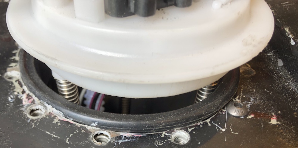
I looked at how the original seal worked. It is a sleeve that fits the diameter of the pump with a compressible o-ring-like seal at the top. The pump hat has a second step that provides a small edge for a sealing surface. The seal did not come with the pump, so I had to source one (OEM was cheapest…$13).
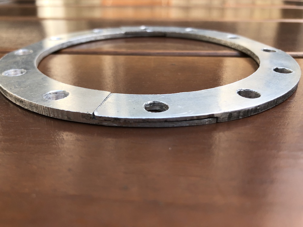
I redesigned the inner ring in aluminum and used rivet nuts to provide the threads for the retaining bolts. The inner radius of the ring had to function as the outer sealing surface, so I split the thickness around two of the rivet nuts to provide half rings I could assemble inside the tank. Lesson learned: rivet nuts will distort aluminum! …I had to tediously bend the ring back to round.
Final Assembly/Retrospect: During the final assembly, I used Permatex Motoseal to seal the inner ring to the tank and the threads (do not use RTV where permanently exposed to fuel!). The existing fuel level float was removed (it was broken anyway) and the one on the new pump altered to reverse the float to clear the inside of the tank. The range for fuel sensor will be reversed but I don’t plan on driving the fuel gauge directly. The original fuel feed at the bottom of the tank was soldered shut.
There was way too much fettling with this assembly! I had to manually correct for sloppy work (or sloppy corrections to good work). The inexpensive pump wound up being more expensive than buying one which included the seal and electrical plug. Ultimately, the design got there and it will work.
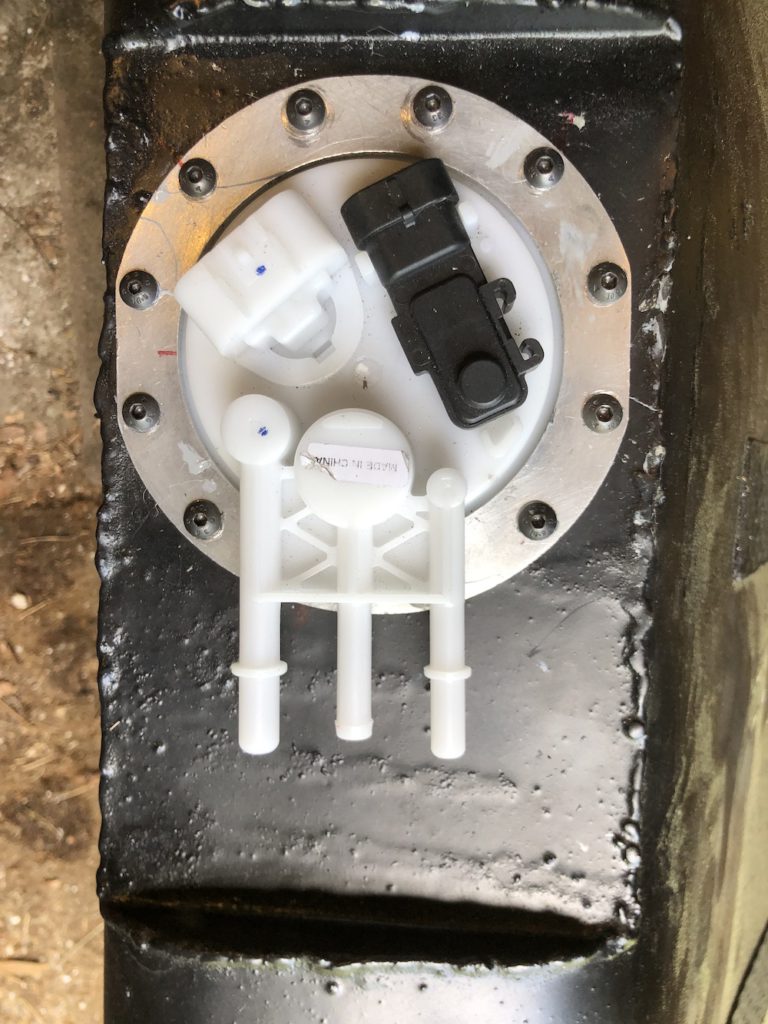
Top electrical connections are left:fuel pump and fuel level (combined) and right: tank pressure (for emissions, unused in this application).
Bottom connectors are left: fuel feed, center: vent and right: fuel return.
