Skip to content
Faulhorn Engineering Works
  • Projects
  • About
CNC

GRBL32, STM32 and other frustrations

  • November 18, 2020January 6, 2021
  • by Christian Stanton

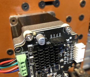
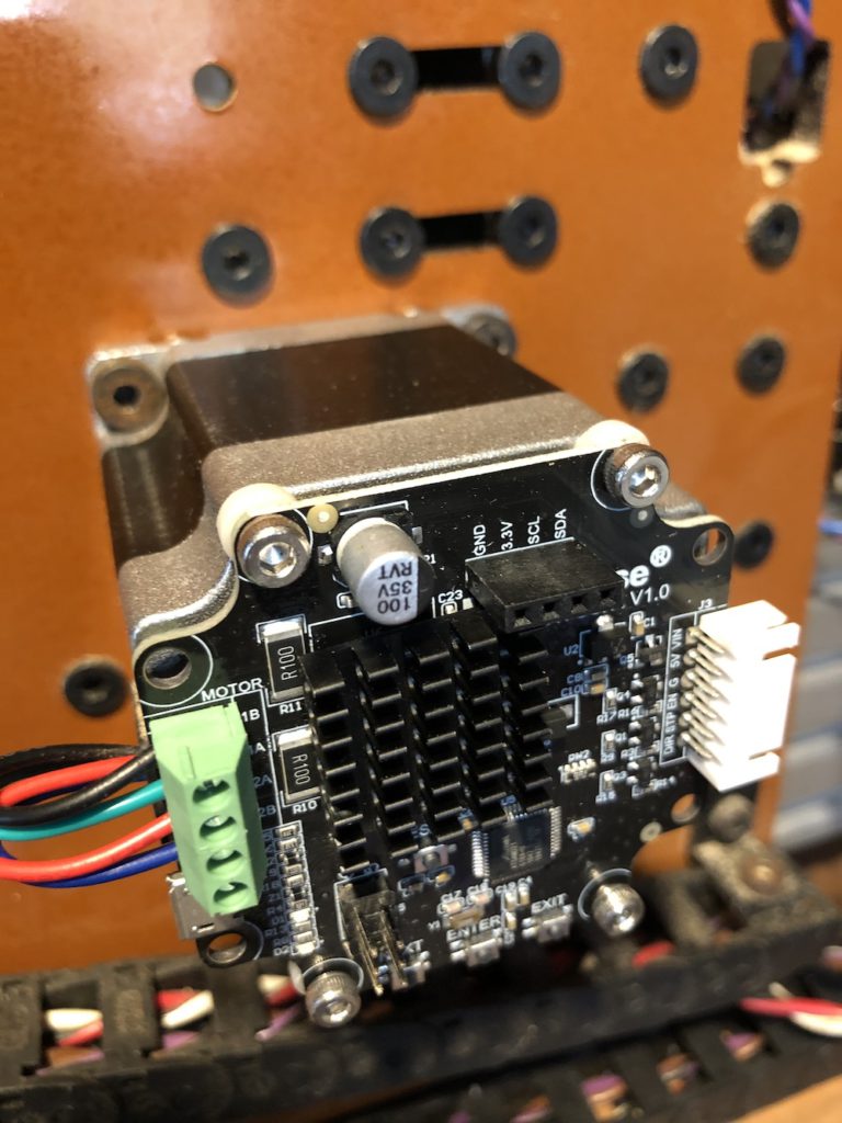
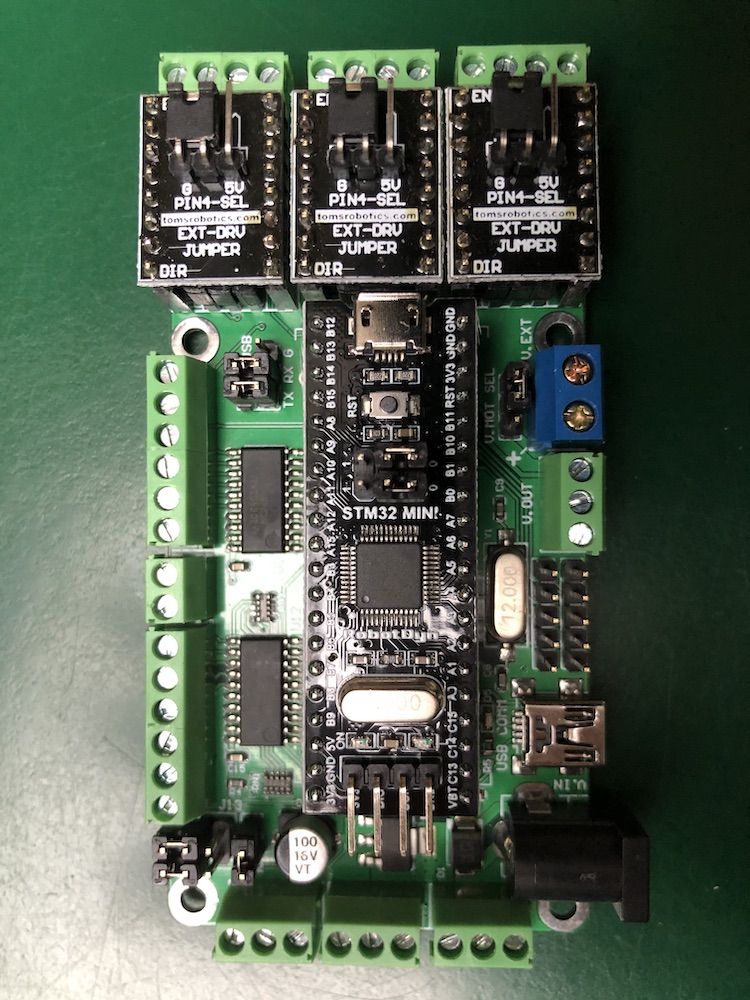
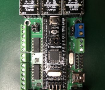
I bought a Tom’s Robotics STM32 based CNC board (F13 – 3 axis) [Note: the jury is still out on this product, as I havn’t gotten it to work and Tom hasn’t responded yet] and finally received the MKS Servo57/42a boards (and a spare) that I blew up. I was eager to bench test it.

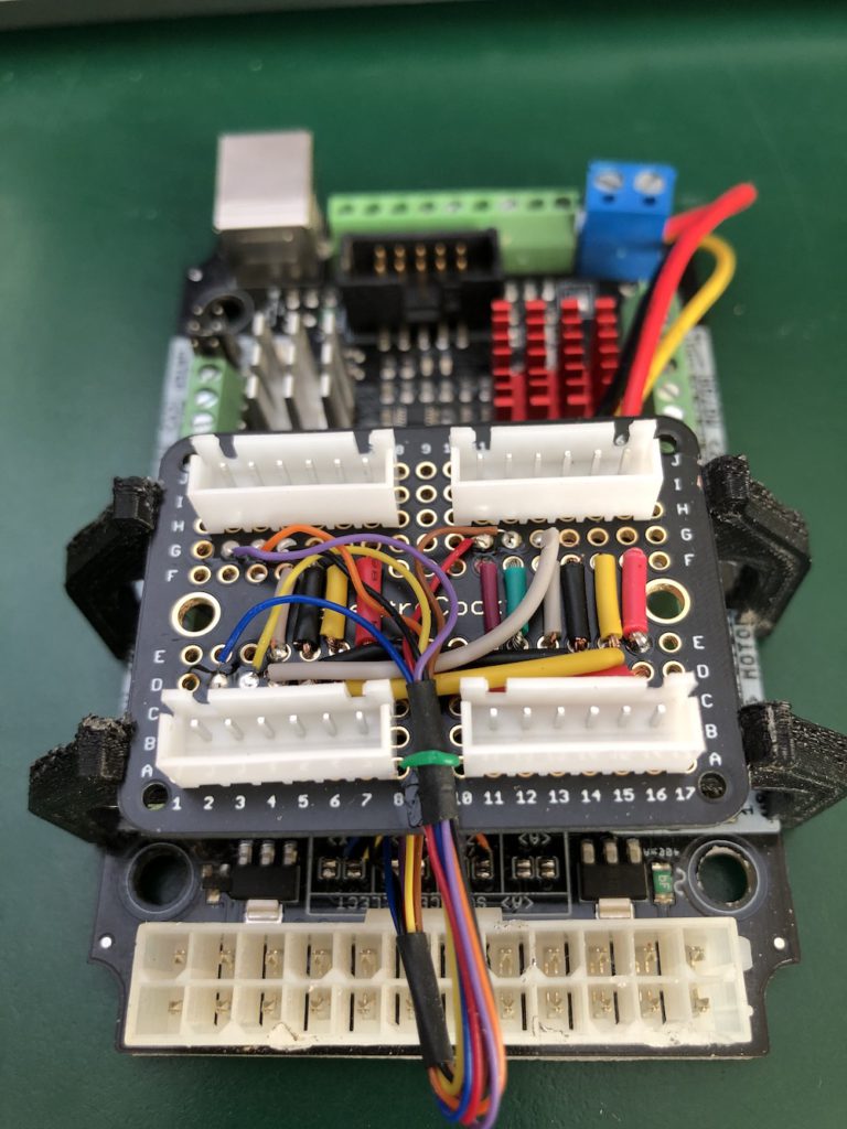
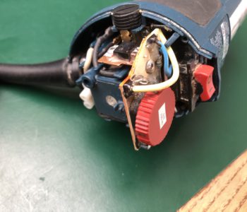
I physically built out the new controller in a new case that holds all the electronics for my CNC router: the CNC board and the 5v PWM to 0-10v converter for the External Brushless Spindle Controller.

Connecting to the board via the USB port and firing up my choice of CNC controller (bCNC in Python), first issue was the baud rate. By default the F13 is set to 921600 which is not a choice in bCNC. Luckily, Tom forked a copy of bCNC and updated this list of baud rates, so I was able to quickly edit the code.

Connected!

I was able to get bCNC to connect and did a few moves with it without any stepper/servos hooked up. All was looking good until bCNC stopped reporting any status or responding to commands. I was able to repeat this several times after a reset of the STM32.

I immediately suspected communications issues, but swapping cables to known good ones did not resolve it.

Is the baud rate too high? Probably not, but Tom does offer to reduce it to 115200 at ship time. I decided to reflash the STM32 with the lower baud rate. This took a bit of setup as I had the build environment is the STM32CubeIDE and the STM32 requires an ST-Link programmer/adapter. The structure of the source code of grbl32 from Tom took me a bit to figure out. It needed two symlinks for grbl and stm32 inside the cubeide directory. (I’m on a PC, so I simply moved the directories).

After a few hours, I had built and loaded grbl32 to the STM32 board with a default baud rate of 115200. More testing and…. (sad trombone) same issue.

Finally a clue…I eliminated the CNC software issue by just using trusted terminal program (PuTTY) to reproduce the problem without any other software involved. I was able to lock it up. When rebooting the STM32 via the reset button, the serial buffer output: Error: 7 just after the reboot. This is a standard GRBL error for EEPROM read failed. Reset and restored to default values. and indeed all the settings I had modified in my testing (speeds and acceleration) were reset to the defaults.

I have another STM32 on order to eliminate a bad board as the cause.

Update 01/06/2021: Tom very graciously sent me another F13 board+Black Pill which exhibited the same issue. I spent about 3 days trying everything I could think of including annotating code for better logging and poking around in the STM32 debugger. It looks like a timing issue as grbl gets confused about the queue counting method of buffer control…. it at some predictable point for a given file grbl32 fails to respond to the host with an OK and the CNC sender stops and waits to send more commands. Ultimately I needed the machine back up and running so I returned both units to Tom and he gave me a full refund. It is an awesome concept and I feel given my depth of skills I should have been able to make it work, but the truth is that it didn’t.

I went back to a cheap Sainsmart grbl 1.1f board that I had in my parts bin that is working fine and I’m building up around that. I’ll swap that out soon as it doesn’t include all the I/O needed. My real work life has picked up, so progress has slowed…. more to come.

CNC

CNC gets Smart(er) Servos… not

  • October 22, 2020November 2, 2020
  • by Christian Stanton

Recently, while milling aluminum on my OX CNC, I had a frustrating number of bad runs because of the stepper motors missing steps. I think this was due to overheating of the 8825 stepper chips on the xPro CNC grbl board. In a fit of pique, I ordered up MKS SERVO57A closed loop stepper boards from AliExpress. These are based on the nano_stepper open source project developed by misfittech. These add a dedicated STM32 controller with to each stepper motor with feedback from a magnet on the shaft. It also provides an optional direct LCD display and menu to setup the servo. It moves the high current driver from the grbl board to the servo board.

The MKS Servo57A
I chose the “A” version because the rated peak amperage is 3A and the steppers are 2.8A. This is set in firmware.
I plan to add a fan/housing to protect the board.
NOTE the handy labeling of the pins on the white connector (doh!).

The feed from the grbl board to the servo board has to now be logic level: STEP, DIRECTION and ENABLE rather than the high current connections directly to the stepper. I had planned this around my memory that I had an xPro CNC v3 which has a breakout connector for logic level STEP, DIR and ENABLE, however when I pulled the board from the CNC, it was a v2 which has no breakout! DOH!

Hack time… The v2 has solder pads used to select which mirror one of the axes (by default Y) to a second stepper motor. This exposes the XYZ(and E not used) axis STEP and DIR. Enable is not directly exposed, but is directly driven from the microcontroller, so I can grab it directly from one of the pins. A bit of delicate soldering of some wire-wrap.

I soldered up a connector board to match the supplied cables for 4 axes (X,Y1,Y2,Z (unused)) and fed power (24v and 5v) and ground. The ENABLE signal is common to all the motors. Some 3D-printed brackets fix the connector board to the xPRO CNC.

The xPro CNC v2 with connector daughter board for the MKS Servo57A.
The solder pads are visible below the connector board.

CAUTIONARY TALE!

After feeling pretty good about the daughterboard for the servos. I reassembled the electronics into the CNC chassis. Hooked up the first y-axis servo and powered up. NOTHING! No display or LED on the servo (there is an OLED that plugs into the SDA connector visible on the top of the board). Perhaps my wiring to that plug is incorrect. Hook the y-axis servo to the z-axis connector. NOTHING! Perhaps the servo is ignoring me. Hook up the second y-axis servo to the y-axis connector. NOTHING! Fall back to testing the z-axis which was to remain a stepper. STEPPER DOESN’T WORK! Start to ring out the supply voltages, 24v is OK. 5v is at 2.25v across the entire xPro board! Check the voltages on the plugboard and they are OK. Check the voltages at the servos and…. CRAP! the cables supplied with the servos swap the pins. 24v was fed into the STEP and ENABLE pins and 5v fed to the DIR pin of the Servos and the xPro board. PZZZZZT!

Tore the whole thing down and tested. Casualties:

  • Fried the xPro CNC drivers on the MEGA328P for pins 1,2,10,11 (YSTEP, ZSTEP, XDIR, YDIR). They now are shorted partially to ground. I did finally get the 5v supply back on the board, but only the un-buggered x-axis works.
  • Fried two of the MKS SERVO57A boards. One won’t power up at all and the other won’t accept steps. The third one was not involved in the incident and works fine.

LESSON LEARNED

Bench test everything incrementally including cables!

No hacking around this ugly, I ordered a new CNC controller (Tom’s Robotics F13) which runs GRBL32 (a 1.1f fork) running on a 32 bit ARM Cortex “Blue Pill” controller. Everything is pluggable on this board vs the xPro which was all SMD. I re-ordered 3 more MKS SERVO57A boards (one spare) and a MKS SERVO43A board (for NEMA17). I may switchout the z-axis for NEMA34). Unfortunately this sets me back a few weeks as the servo boards are shipping from AliExpress China.

Tom’s Robotics F13 – Received in three days… now the long wait for the AliExpress parts.

CNC

Router Hacking

  • May 27, 2020November 2, 2020
  • by Christian Stanton

In starting the Quarinjection project, I knew that it involved some custom fabrication of brackets, covers, etc. One of my existing skills and resources was a small CNC router that I built a few years ago from an Openbuilds OX design. Ideally I could CNC some aluminum parts. It’s perfectly capable of cutting aluminum, it’s just a trickier material than wood.

The problem: The spindle I have is a 1hp Bosch Colt PR20EVS router. The Colt works well for routing wood but aluminum requires a much lower spindle speeds. The stock Colt router runs 16K-35K RPM. Too high a surface speed (speed of the flute through the material) to cut chips and not just stir weld the aluminum (which I did a lot of trying to get this to work). I needed a maximum minimum(?) speed of around 10K RPM to achieve a surface speed of ~350ft/min with an 1/8″ bit. (The ideal speed for 6061 Aluminum is about 280SFM)

The Colt has a built in speed controller (via a thumb dial at the top) which I figured I could modify to lower the minimum speed without making it unusable. The motor is a 110v AC brushed which have limited torque ranges, so I’d be sacrificing a bit of torque at lower speed.

I measured the speed before taking it apart. (I’m measuring off of the collet nut, but one flat is painted white).

Stock minimum speed was 13K, lower than the spec 16K.
Maximum was also lower than the spec at ~30K.

Surgery!

Hard to see, but the chip on the left is an Atmel U2008B – Low cost AC Phase Controller.
I was never able to identify the other chip, but my guess is some sort of opamp.

Time for a bit of reverse engineering… luckily a simple single sided board which was not buried in potting compound. The core of the speed control is an Atmel U2008B – Low Cost AC Phase Controller. The chip is the one on the left in the picture above. This manages speed via phase shift and provides soft start and some load correction (so as the router gets loaded the RPM stays the same). The large Triac on the heat sink at the top of the board does the load switching.

The Red thumb wheel, a 2.5Kohm rheostat, is in series with a base resistor R7, which measures 2.5Kohm. Setting 1 is 5K=13000RPM, and setting 6 is 2.5K=30000RPM.

The marking on the SMD resistor of 398 threw me for a while (3900MOhm?), but this is a EIA-96 coded resistor sloppily marked 39D=2.49K. These resistors are 0603 sized (6mm x 3mm) which is hard to show just how tiny this is (think grain of pepper sized). Resistor assortments are available and inexpensive ($0.01/ea)

Minimum speed was at 5K total resistance, maximum at 2.5K so an increase in resistance would reduce the overall speed. Replacing R7 with the next stock value of 3.3K (EIA-96 51D) for a total resistance of 6.3K. This should give me a 25% (6.3K/5K) reduction in speed overall or 10,400K RPM minimum (assuming it’s roughly linear). To jump to the next value (5.1K) that I had on hand meant the adjustable range would get too low.

A bit of finicky soldering later…

Speed reduced to 10,300RPM minimum. Maximum is now about 21K RPM.

Success! The router doesn’t seem to be bothered by the change and runs normally at the lower speed. Off to cut aluminum!

Afterthought: I will eventually buy a true CNC spindle for this rather than mucking around with modifying a router, but for $8 I was able to get this to work.

Recent Posts

  • Realistic STA-2100D Restore
  • GRBL32, STM32 and other frustrations
  • CNC gets Smart(er) Servos… not
  • Quarinjection Selecting an ECU
  • Quarinjection Throttle Position Sensor

Recent Comments

    Archives

    • April 2022
    • November 2020
    • October 2020
    • July 2020
    • June 2020
    • May 2020
    • March 2020

    Categories

    • CNC
    • projects
    • quarinjection
    • stereo recap
    Theme by Colorlib Powered by WordPress