Skip to content
Faulhorn Engineering Works
  • Projects
  • About
quarinjection

Quarinjection Selecting an ECU

  • July 1, 2020August 5, 2020
  • by Christian Stanton

At the beginning of the Quarinjection project, one of the major decisions was what ECU to use. There are only a handful of open-source ECUs that would make the cost feasible for the project. All the proprietary ECUs would cost the entire budget of the project.

RusEFI – Frankenstein, Frankenso, Prometheus, Proteus, Hellen…
These use SMD assembly which leads to a compact, clean board but is difficult to assemble. Based on the stm32f407 ARM development board and running ChibiOS/RT. Code is in C/C++ which is ideal as I have deep experience (not that there is any need to rewrite code).

Megasquirt
The first commercially available (2002) implementation of EFI using a microcontroller. Still sold, but built around on the older 68HC908 processor and the source code is not intended to open source. This has a different audience and there are many PnP versions for different cars. Only assembled boards and are 4-5x the cost of these others.

Speeduino
An interesting project for an open source EFI based on Arduino Mega. Less powerful than the stm32f407 which limits functionality and flexibility, but it should be good enough to work for this application. I’ve been doing quite a bit of Arduino (which is a wrapped C) lately and this is also comfortable.

I spent a few hours thinking about this and ultimately decided that the Speeduino BOM came out a bit cheaper and uses discrete components and the openness of both the platform and the software is attractive. And I already had an Arduino Mega clone in my parts box.

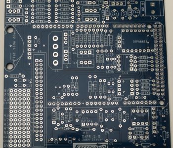
I bought a bare v0.4 board and VR conditioner from ebay (turns out it shipped from Israel) for <$15. It took about 2 months to arrive 🙁 after being lost once. I decided it was never going to arrive and ordered another board from a US supplier and… they both arrived a day apart.

I sourced components from my favorite new (to me) supplier: Mouser Electronics. Occasionally they don’t have something I’m looking for that are peripheral to core electronics (like Diametric magnets) but everything has been easy to find and compare, shipping is instant and customer service is great. Digikey is good also and they are my fallback. I think the BOM, including $14 of extraneous R&D components for my rainy day shelf came to $100.

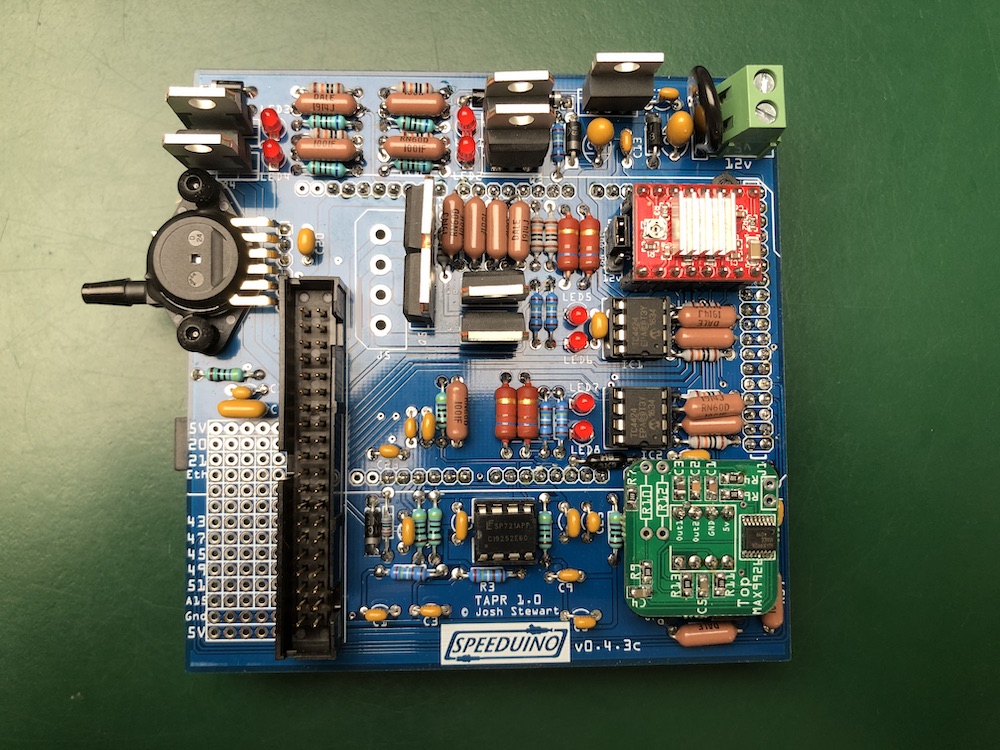
I don’t know why, perhaps a return to my youth of assembling RadioShack kits, but I find assembling electronics very calming and satisfying. I savored the build of the Speeduino board. Here it is complete with the VR (variable reluctance) driver board for the cam/crank sensors and the stepper motor driver for idle control (which won’t be used in the initial build). I don’t know why some of the resistors spec’d are oversized (the brown blobby things) but I made them fit as well as possible. The Speeduino is just an Arduino ‘hat’ and underneath this board (you can see the pin outline) is an Arduino Mega clone. J5 is a high-amp output which I did not put a connector on yet because I’m not sure I’ll use it.

quarinjection

Quarinjection Throttle Position Sensor

  • June 4, 2020October 21, 2020
  • by Christian Stanton

I chose to re-use the current Solex 28/32 PDSIT-4 carburetor rather than purchase a new throttle body. The carbs role to meter and deliver fuel will now be done by the fuel injectors, so the carb only needs to function as a throttle plate and provide the ECU with the throttle position.

I stripped down the existing carb by removing the fuel bowl, automatic choke and venturi and then used epoxy to fill any unneeded fuel or air passages.

Stripped Solex Carb, throttle linkage side. The threaded mounting holes at the top are for the automatic choke which I am reusing for the TPS sensor.

The Throttle Position Sensor (TPS) is a potentiometer that rotates the same ~90 degrees as throttle plate. The position is then read by the ECU. The task is to interface the current throttle movement to the TPS which is normally connected directly to the throttle shaft on the opposite side to the cable/linkage. On the Solex the plate turns the opposite direction to the TPS I have (from a Honda throttle body $10), so it has to mount on the same side as the linkage (or geared to the shaft) . Space is also very limited around the manifold mounted carb.

Throttle Position Sensor – Inside

There are existing threaded mounting holes where the old choke was that I can use to attach the TPS. I designed a mount and lever system that uses the choke lever on the throttle shaft.

The existing throttle lever (lower left) to TPS (top plate) mount and linkage. Only critical detail has been modeled and the bent tabs on the lever are shown flat. The lower bolt intentionally has no spacer to clear the lever.
Assembly installed. Still needs some means of retaining the linkage. The linkage, salvaged from the fuel level float, is 2.5mm, which is again an uncommon size.

Retrospect:

Milling: I was very pleased with the milling now that I have the feeds and speeds dialed in. The dimensions of the holes were slightly small which means I probably have a calibration issue with grbl. I had my doubts about routing a 4.7mm hole with a 3.175mm mill. It works without air clearing but does regrind some chips. I am not doing finishing passes as the double stick mounting tape I’m using can’t take the force after it’s cut free from the sheet.

Design: Version 1 worked as planned and I didn’t have to redesign or recut anything. The full range of motion was just possible with the design, so I should have rotated the lever another 5 degrees counter clockwise. 3003 aluminum is too soft (“tends to be gummy when machined“) for tapping and just kind of smears into a badly formed thread. Next time I’ll use brass or steel press fit inserts. The tapped holes on the carb were metric but done in the 60’s before there were standard sizes, so they are an odd M5x0.75; I retapped these holes to M5x0.80 without losing much integrity. I should have modeled the full throttle lever as it is very close to the lower low-profile bolt for the TPS (there is another lever on the opposite side of the throttle shaft which I may use instead). This is a temporary solution just to get the system to work and then I’ll redesign the entire inefficient intake manifold.

Overall success! On to other components…

quarinjection

Quarinjection Ignition

  • May 30, 2020July 1, 2020
  • by Christian Stanton

The ignition coil generates spark and the distributor distributes it to each spark plug. The distributor also varies the timing of the spark based on the speed of the engine (via a set of centrifugal weights) and the load / requested speed of the engine (via the vacuum advance).

The ECU will now control the timing of the ignition, so I only need to generate a spark and get it to the right spark plug. Modern EFI no longer uses the mechanical distributor but individual coils to deliver spark. You can use one coil for each plug or one coil for two plugs (wasted spark).

Neutering the distributor: It made sense to put the coil pack in the same place that the old distributor was located but first I had to eliminate the distributor. It can’t just be removed as the shaft also drives the oil pump.

I cut the distributor housing at the flange and shortened the shaft to sit slightly below the surface of the housing. The lower shaft is supported by an oil pressure bearing. The shaft is thrust downward by the gear geometry and there is an axial bearing surface on the gear. There is a bushing in the top of the distributor housing which I felt was unnecessary now that there is little stress on the shortened shaft.

I’ll fabricate a cover and gasket for flange.

Spark source: I needed a coil that supported 4 cylinders and had a built in igniter. The igniter isolates the high voltage circuit and provides a low voltage interface to the ECU. I chose an ignition pack from 1998-2001 Volkswagen Golf for $15.

I fabricated a mount from sheet steel to locate it near the old distributor location.

Spark delivery: I thought I was going to be able to reuse the ignition wires, but the plugs on the coil are different. The most cost efficient way to replace them was to buy a set of VW/Audi wires ($18) that were compatible with the coil pack and replace the spark plug ends with the correct plug socket ($7). Although there are specialized crimpers, you can get away with some artful work with needle nose pliers. The core is just folded back over the wire.

Ready to be hooked to the ECU!

You can see the top of the distributor flange and shaft just below the coilpack.

quarinjection

Quarinjection Fuel Pump

  • May 29, 2020July 1, 2020
  • by Christian Stanton

Modern fuel injection systems run at ~45PSI, much higher than the ~4PSI supplied by the existing mechanical pump. The easiest solution would have been an external pump hooked to the existing fuel line but this wound up more expensive than using a common submerged in-tank pump.

The existing Sonett fuel tank sits directly behind the driver and is an unusual shape for a tank. It is tall and narrow rather than flat.

The tank is ~14″ deep. After a lot of research and cost optimization later… a Chevy 1500/2500/3500 fuel pump from 1997-2000 has the correct size and fuel layout. It is an unregulated pump with a return and vent line with a roll-over valve and correct depth. The supply volume and pressure will work for the regulator and injectors I’m using. As a bonus it includes a fuel level sensor. All for $28! (see below)

The shape of the top of the tank is too narrow to fit the mounting hole for the pump and there is very limited clearance on top of the tank, so I had to recess a flange into the tank.

DO NOT WELD FUEL TANKS! (without knowing exactly what you are doing!). This tank was dry for 15 years and washed out with water based degreaser. If I had any doubt I would have filled the tank with water up to the part I was welding.

Lesson learned: After a bit of ugly MIG welding (and I ground the welds which was a mistake and then re-welded them which was another mistake), The welds were porous and would not seal up. I resorted to a coating POR-15 fuel tank sealer inside and out to seam seal the welds.

Designing the mount: Normally these pumps have a formed flange and a twist lock retaining ring. This is not something that is easily sourced without buying an entire fuel tank. (although I found something close here) I used a design used for other flange mounts with a split internal ring with captured nuts and an external ring to retain the pump. A flat flange seal (below in white) seals the pump to the tank.

Design for Fuel Pump Mount

Fail/Revise/Repeat: I built a split “C” ring of sheet steel and welded M5 captured nuts to it. The gauge on the steel was too light and the M5 about as small as I could weld with MIG. After installation, I realized that the large flat flange seal would not seal up with the amount of pressure that I could torque the screws to and the gap in the “C” ring left part of the flange unsupported. Lesson learned: A small footprint seal (like an o-ring) works better with low pressure flanges and non-machined surfaces.

I looked at how the original seal worked. It is a sleeve that fits the diameter of the pump with a compressible o-ring-like seal at the top. The pump hat has a second step that provides a small edge for a sealing surface. The seal did not come with the pump, so I had to source one (OEM was cheapest…$13).

OEM Fuel Pump Seal

I redesigned the inner ring in aluminum and used rivet nuts to provide the threads for the retaining bolts. The inner radius of the ring had to function as the outer sealing surface, so I split the thickness around two of the rivet nuts to provide half rings I could assemble inside the tank. Lesson learned: rivet nuts will distort aluminum! …I had to tediously bend the ring back to round.

New inner mounting ring with split, before rivet nuts

Final Assembly/Retrospect: During the final assembly, I used Permatex Motoseal to seal the inner ring to the tank and the threads (do not use RTV where permanently exposed to fuel!). The existing fuel level float was removed (it was broken anyway) and the one on the new pump altered to reverse the float to clear the inside of the tank. The range for fuel sensor will be reversed but I don’t plan on driving the fuel gauge directly. The original fuel feed at the bottom of the tank was soldered shut.

There was way too much fettling with this assembly! I had to manually correct for sloppy work (or sloppy corrections to good work). The inexpensive pump wound up being more expensive than buying one which included the seal and electrical plug. Ultimately, the design got there and it will work.

Final Pump Mount (Sealed!)
Top electrical connections are left:fuel pump and fuel level (combined) and right: tank pressure (for emissions, unused in this application).
Bottom connectors are left: fuel feed, center: vent and right: fuel return.

quarinjection

Quarinjection Basic Requirements

  • May 28, 2020July 1, 2020
  • by Christian Stanton

It would be easier to build out the Quarinjection project if I just sourced a bunch of parts designed for the DIY-EFI/Hotrod market. However, one of the challenges of this project was to design robustly on as thin a budget as possible. I sourced off the shelf items designed for high volume production cars which will make the engineering/integration more challenging, but lower the overall cost by allowing me to source from any suitable vehicle and aftermarket manufacturers.


What is needed to run an engine with Electronic Fuel Injection? It’s no different than the 60’s technology that the engine runs on now. You need the proper ratio of fuel and air and a well timed spark.

Existing Engine

Fuel Delivery – Pump: The little V4 has a physical diaphragm fuel pump driven by an eccentric lobe on the camshaft. This sucks gas from from the fuel tank and delivers a few PSI of pressurized fuel to the carburetor.

Fuel Delivery – Carburetor: The V4 has a Solex 28/32 PDSIT-4 carburetor. This regulates the amount of fuel by taking into account the temperature and load on the engine as well as the movement of the accelerator pedal. The carb functions as both ‘sensors’ and the ‘control mechanism’. It is an analog calculator.

Spark Delivery – Generation: The spark is supplied by the ignition coil. It’s similar to transformer (with a trick) to go from 12 volts to 40,000-50,000 volts. The trick is that when you remove the supply voltage from the coil, the magnetic field collapses and generates the high voltage spark.

Spark Delivery – Timing: The V4 has a Bosch distributor which regulates timing of spark based on engine RPM and engine load. It is another analog calculator.

Electronic Fuel Injection

To replace the functions of the existing engine with modern EFI, these are the elements needed:

  • Fuel Delivery
    • Fuel Pump
    • Fuel Lines
    • Injectors
  • Spark Delivery
    • Ignition
  • Sensors for engine load, timing and temperature
    • Throttle Position Sensor (TPS)
    • Manifold Pressure (MAP)
    • Crankshaft Position Sensor
    • Camshaft Position Sensor
    • Inlet Air Temperature (IAT)
    • Coolant Temperature (CLT)
  • An ECU computer to coordinate the sensors and delivery
    • Computer Selection

Recent Posts

  • Realistic STA-2100D Restore
  • GRBL32, STM32 and other frustrations
  • CNC gets Smart(er) Servos… not
  • Quarinjection Selecting an ECU
  • Quarinjection Throttle Position Sensor

Recent Comments

    Archives

    • April 2022
    • November 2020
    • October 2020
    • July 2020
    • June 2020
    • May 2020
    • March 2020

    Categories

    • CNC
    • projects
    • quarinjection
    • stereo recap
    Theme by Colorlib Powered by WordPress